Flow Indicator Maintenance & Safe Use Instructions
CONTENTS
Our Products

Preface
BATUSAN is committed to personal safety and the long service life of the SIGHT GLASS with this instruction manual, and it is most important that you review the Installation and Operation Manual. This Flow Indicator Maintenance manual will provide all necessary safety guidelines for valves, including information on handling, installation and operation of the valve. Please read it carefully before installing or maintaining the valve.
BATUSAN provides general guidelines in this manual. The end user must therefore take responsibility for the correct valve selection, sizing, installation, operation and Flow Indicator Maintenance of Batusan valve products. The end user must read this document in conjunction with the instructions supplied with the product.
Purpose
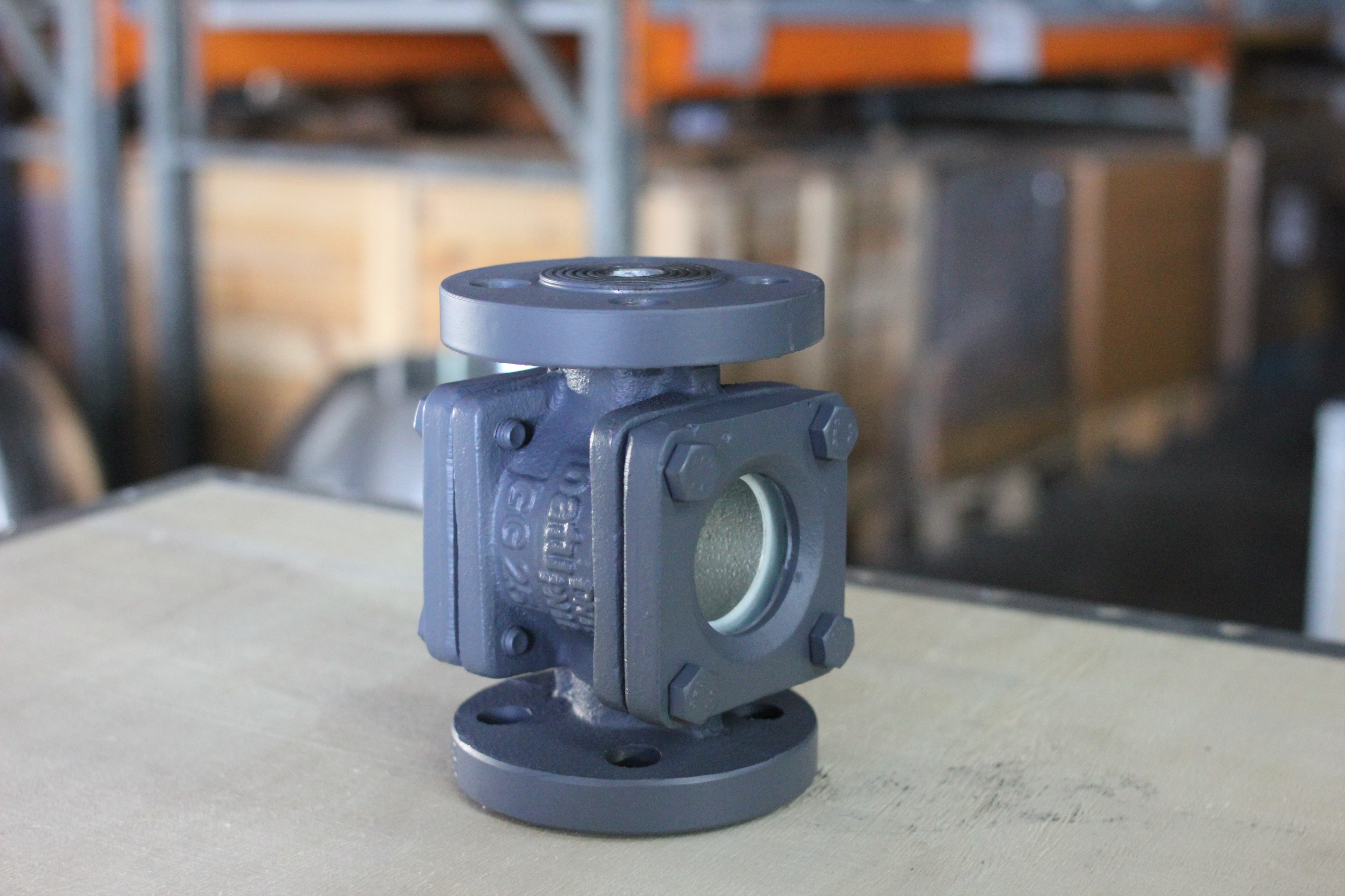
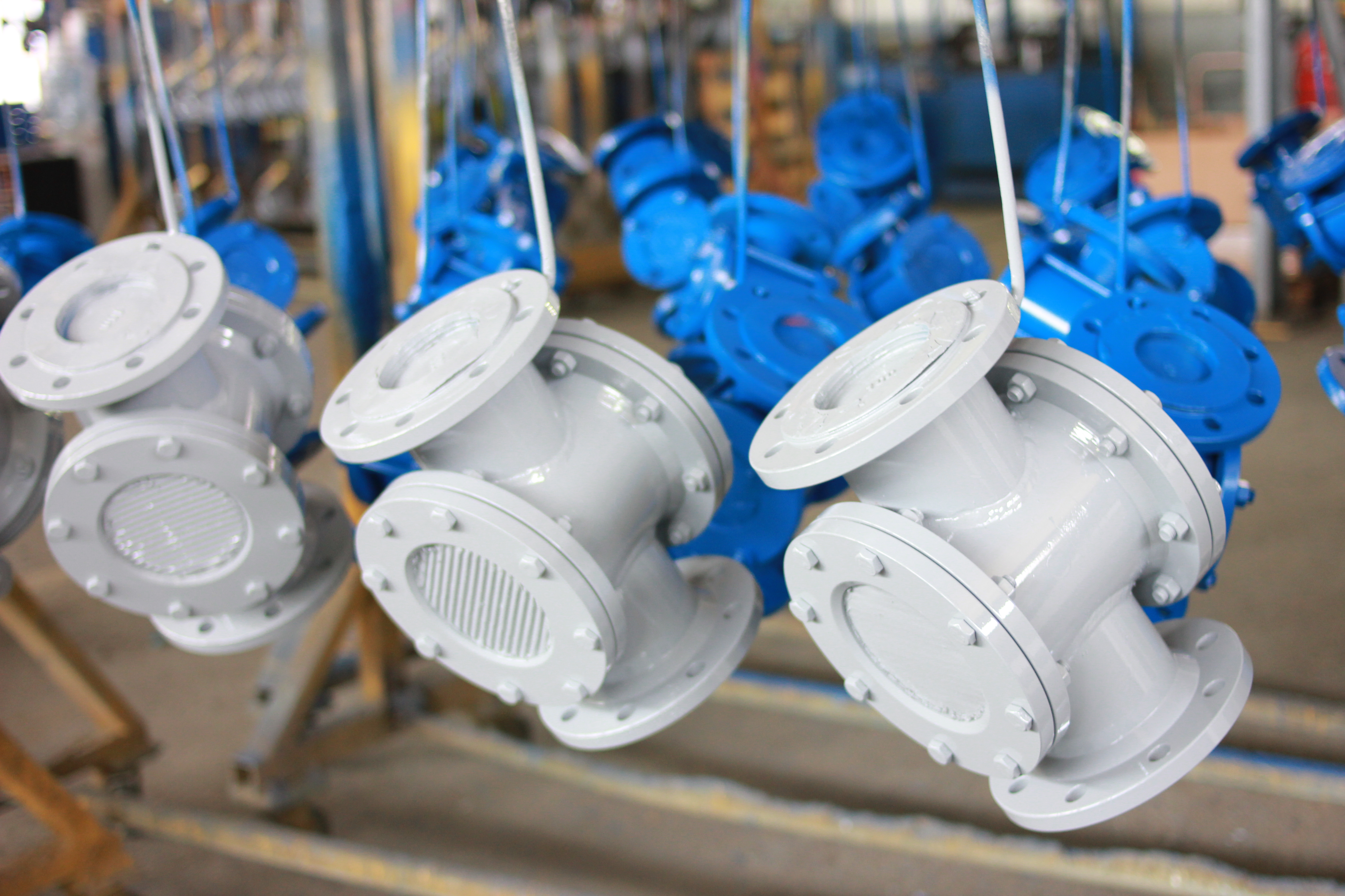
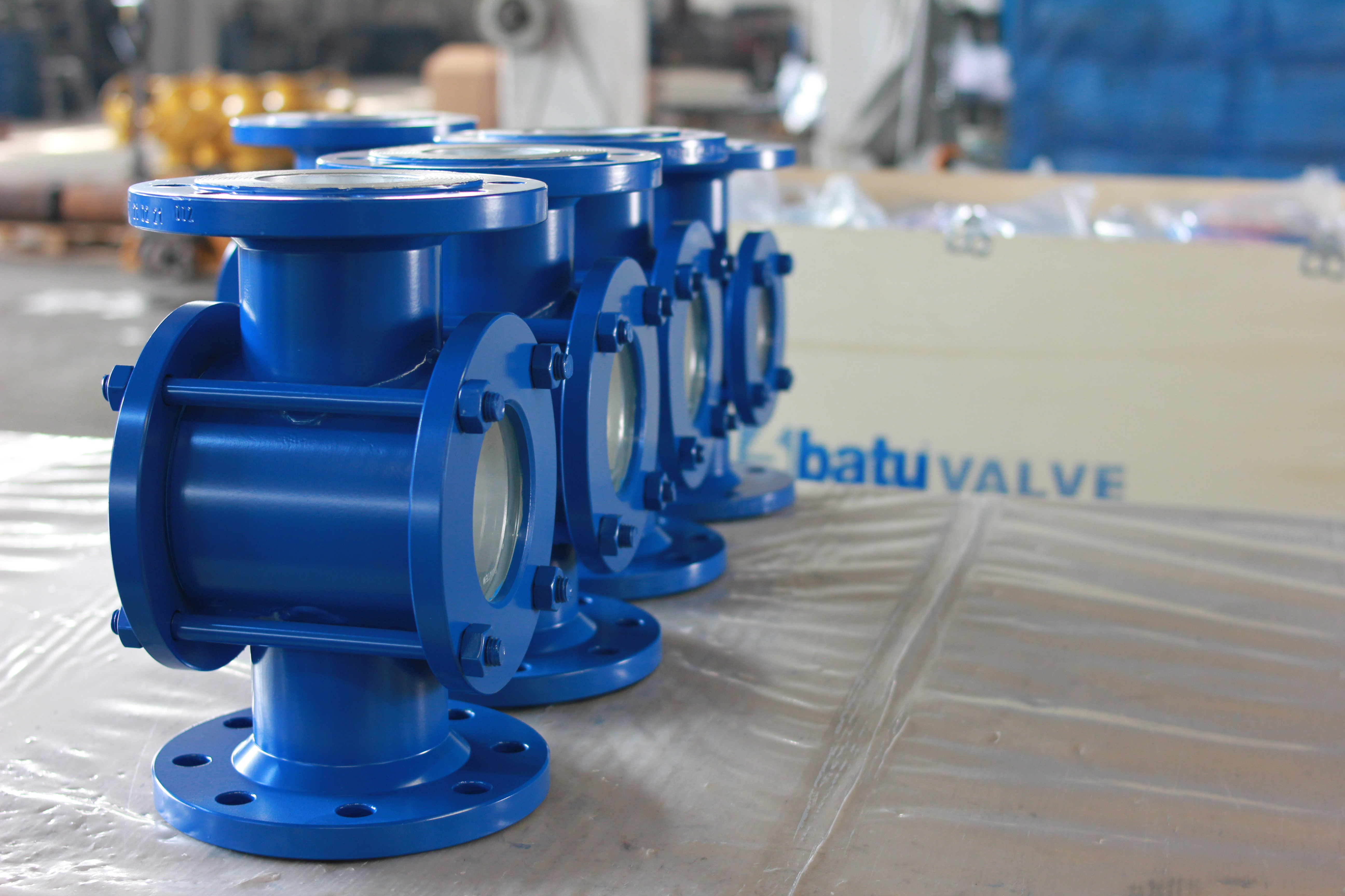
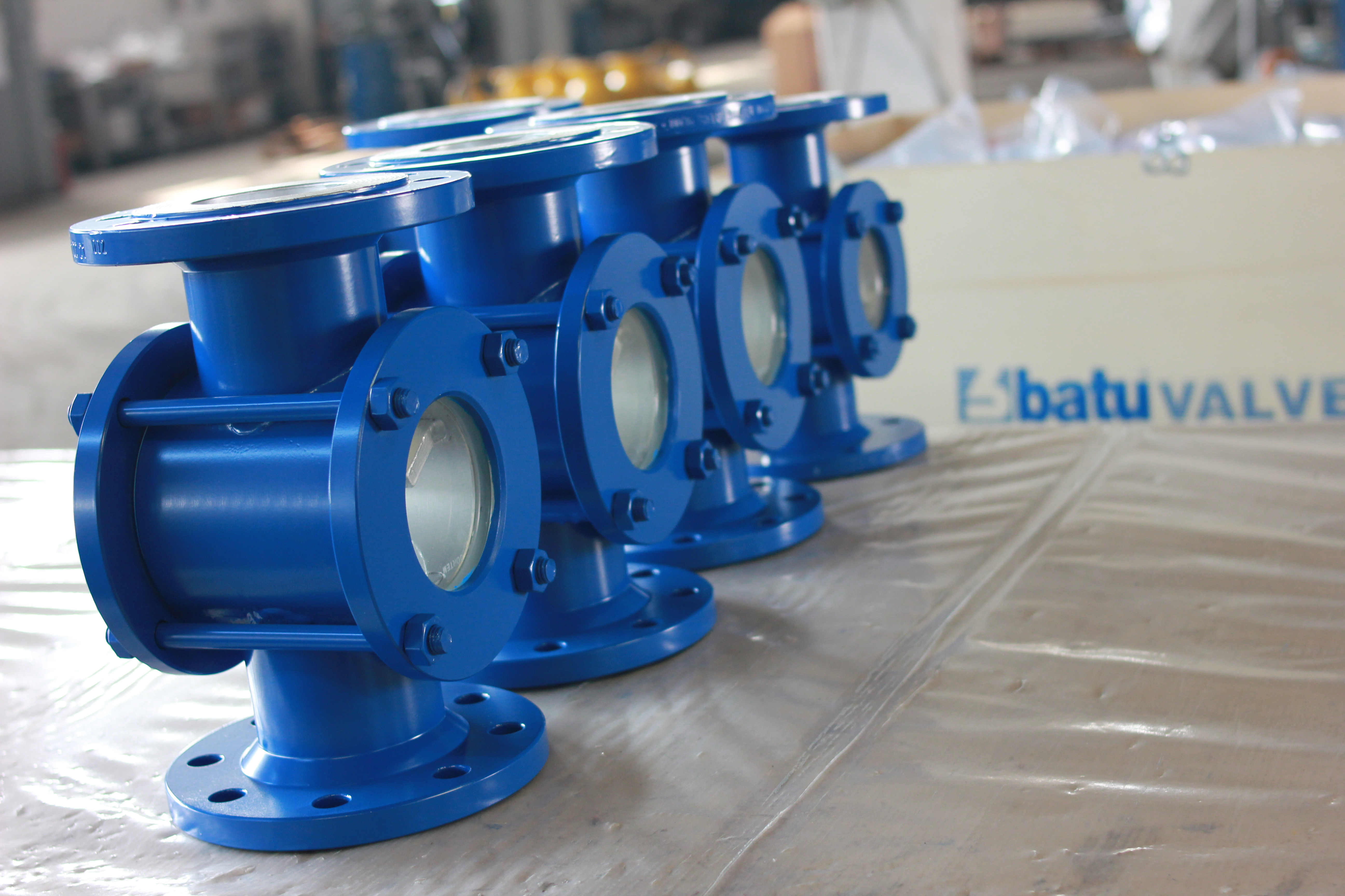
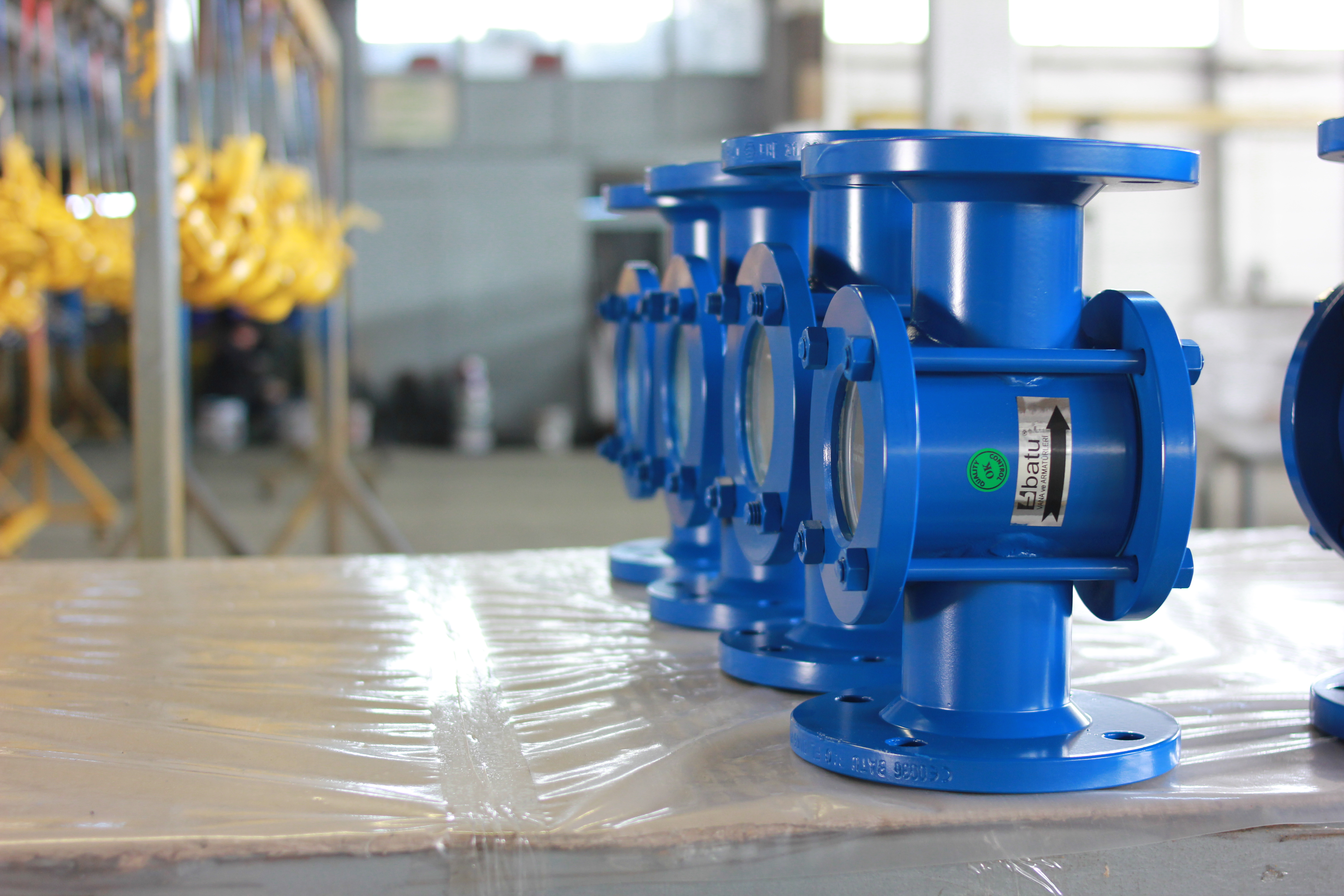
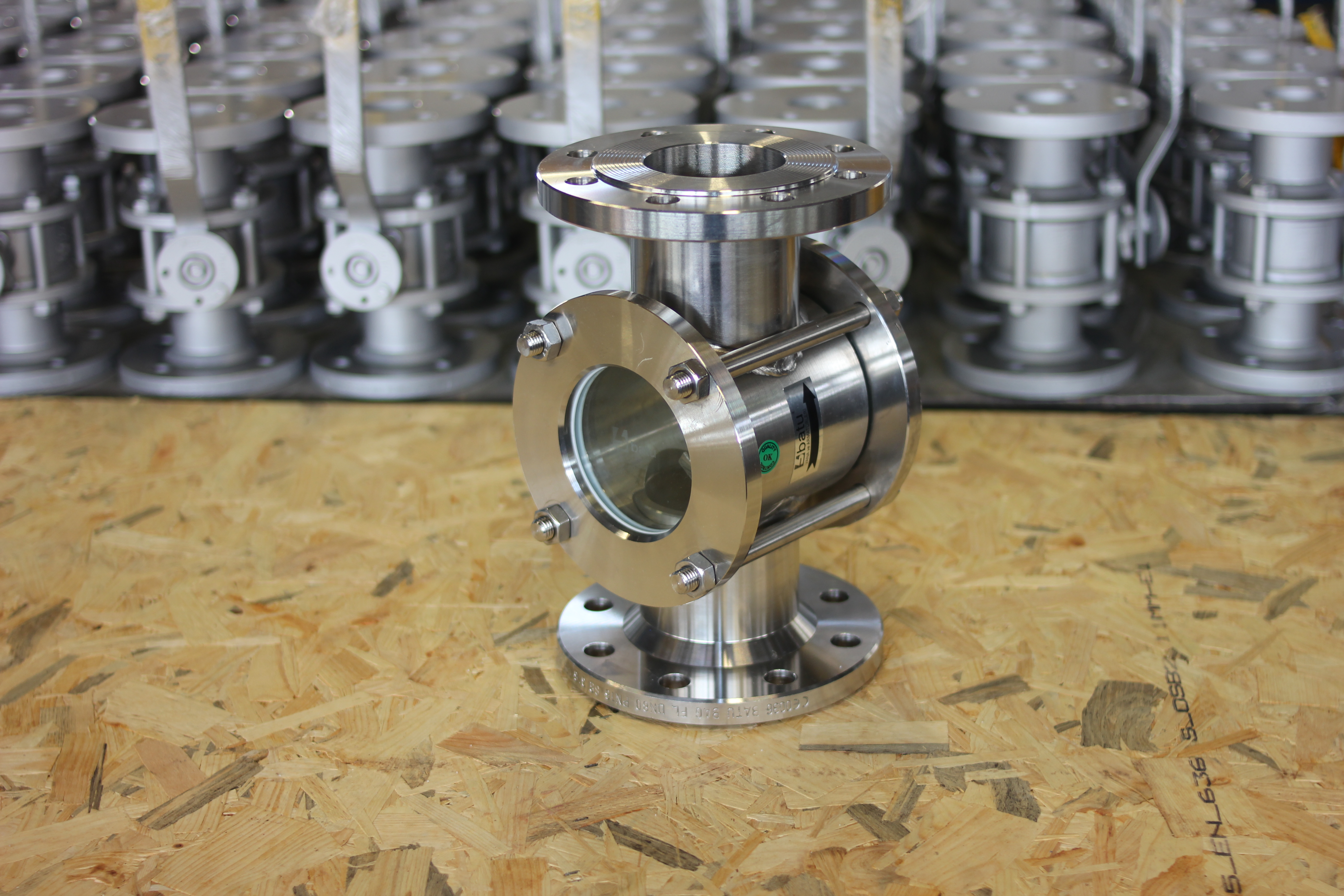
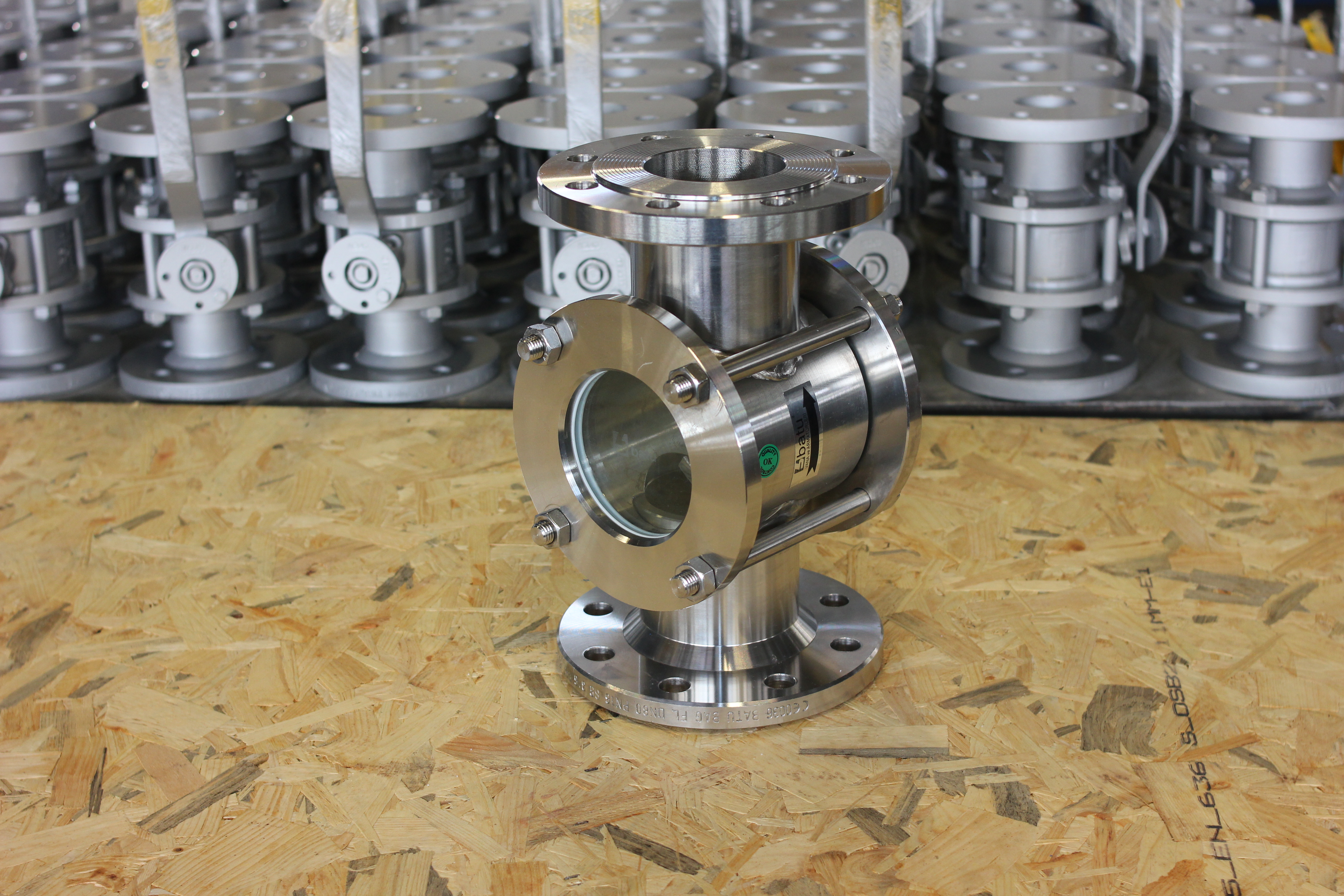
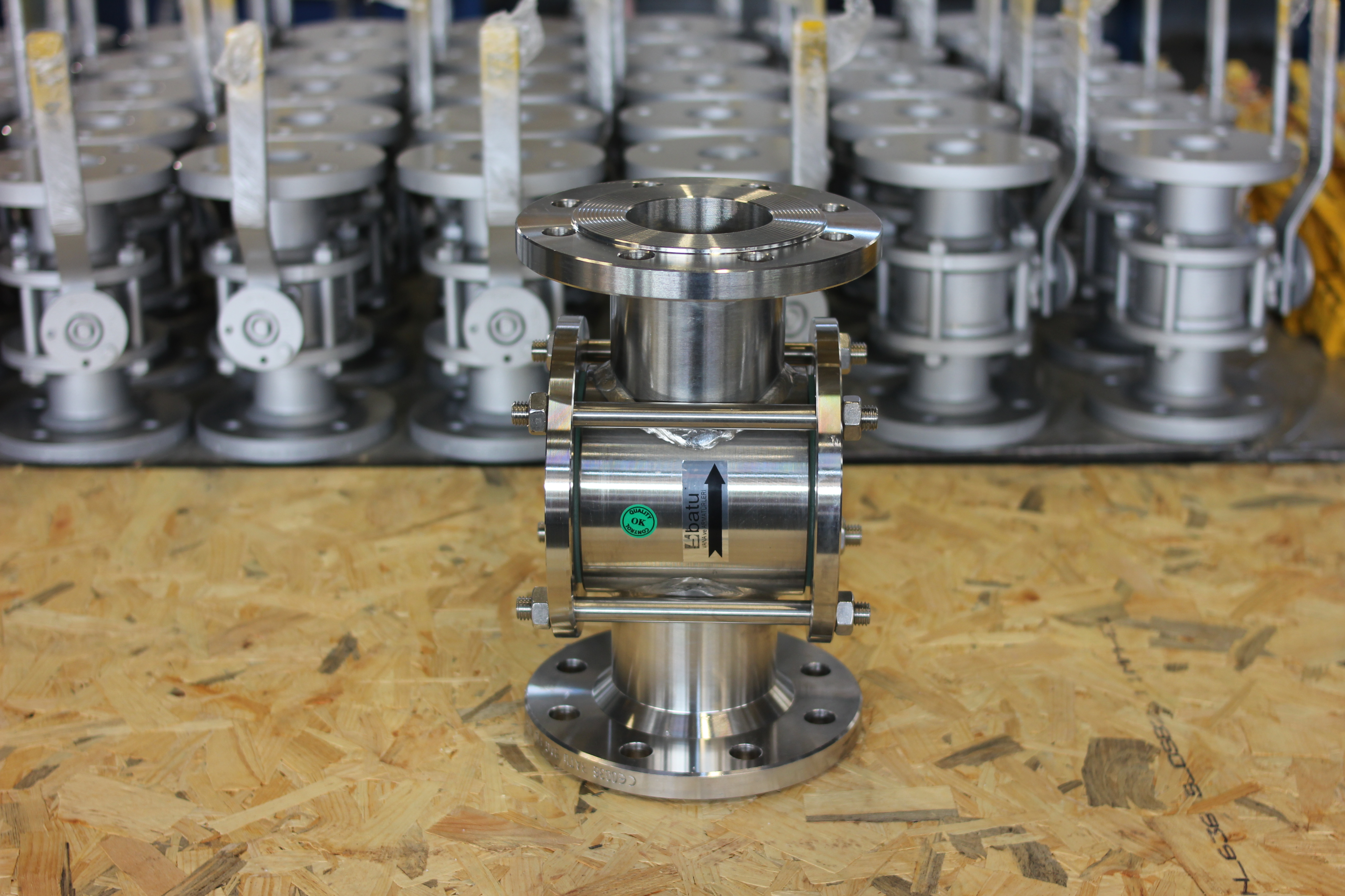
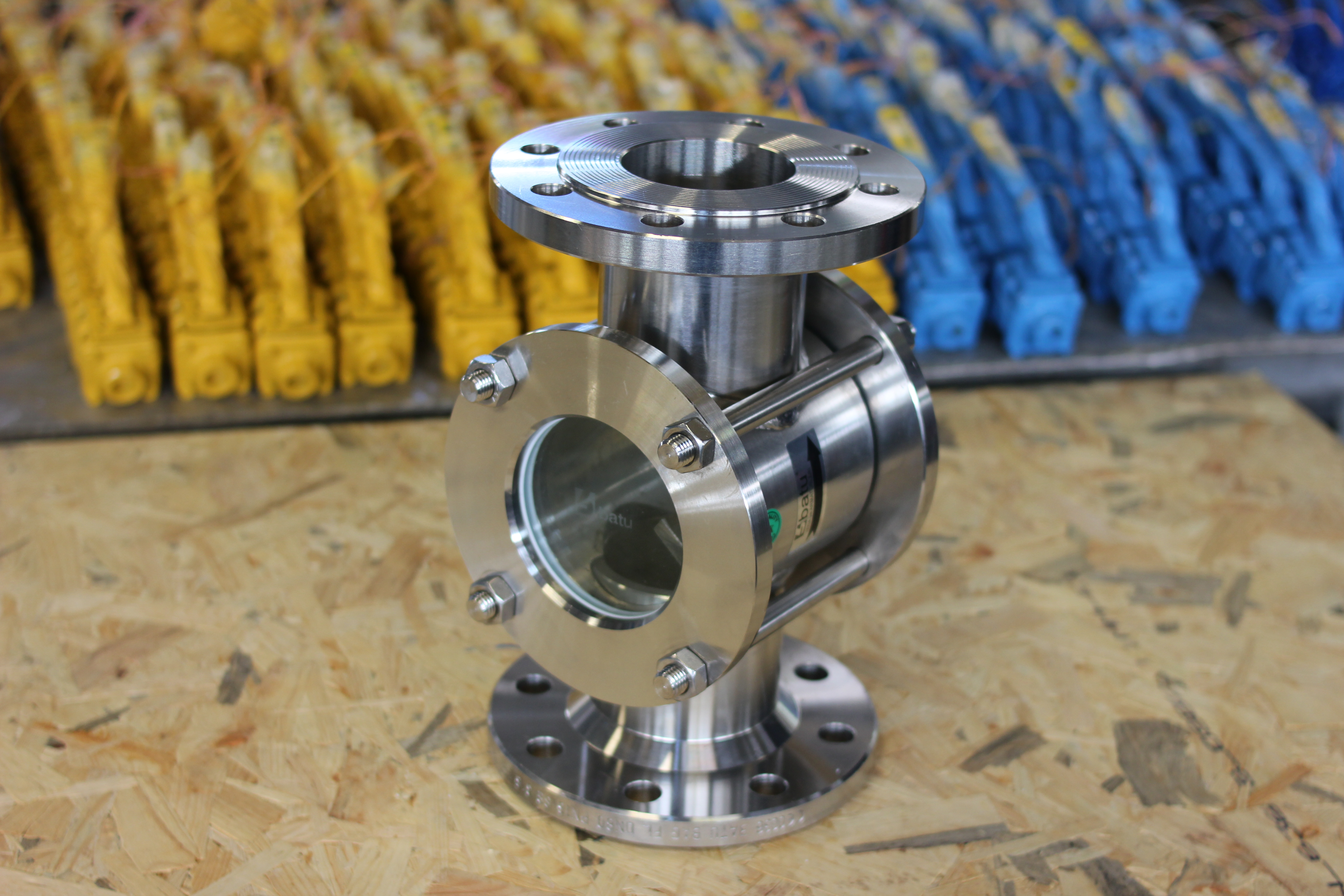
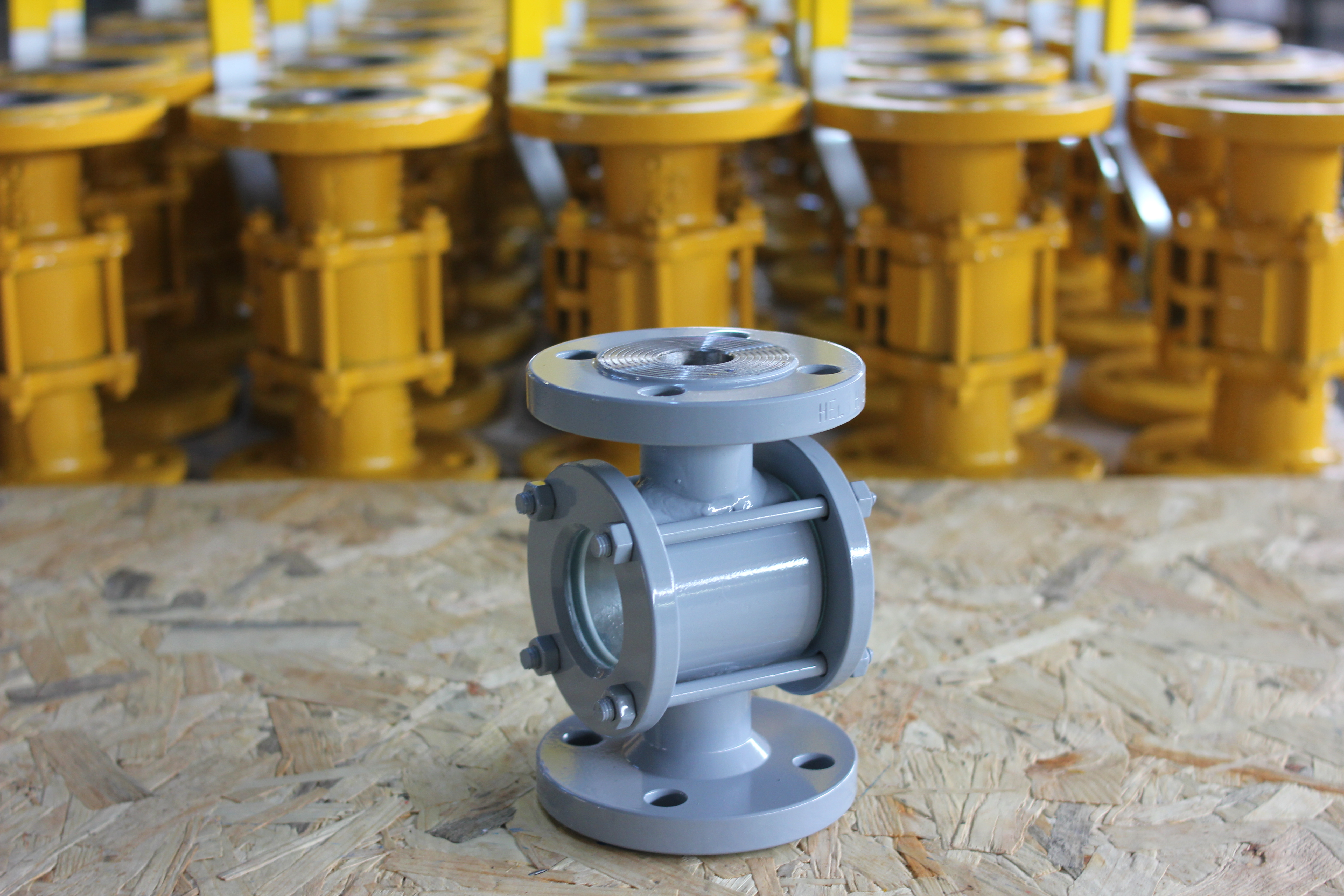
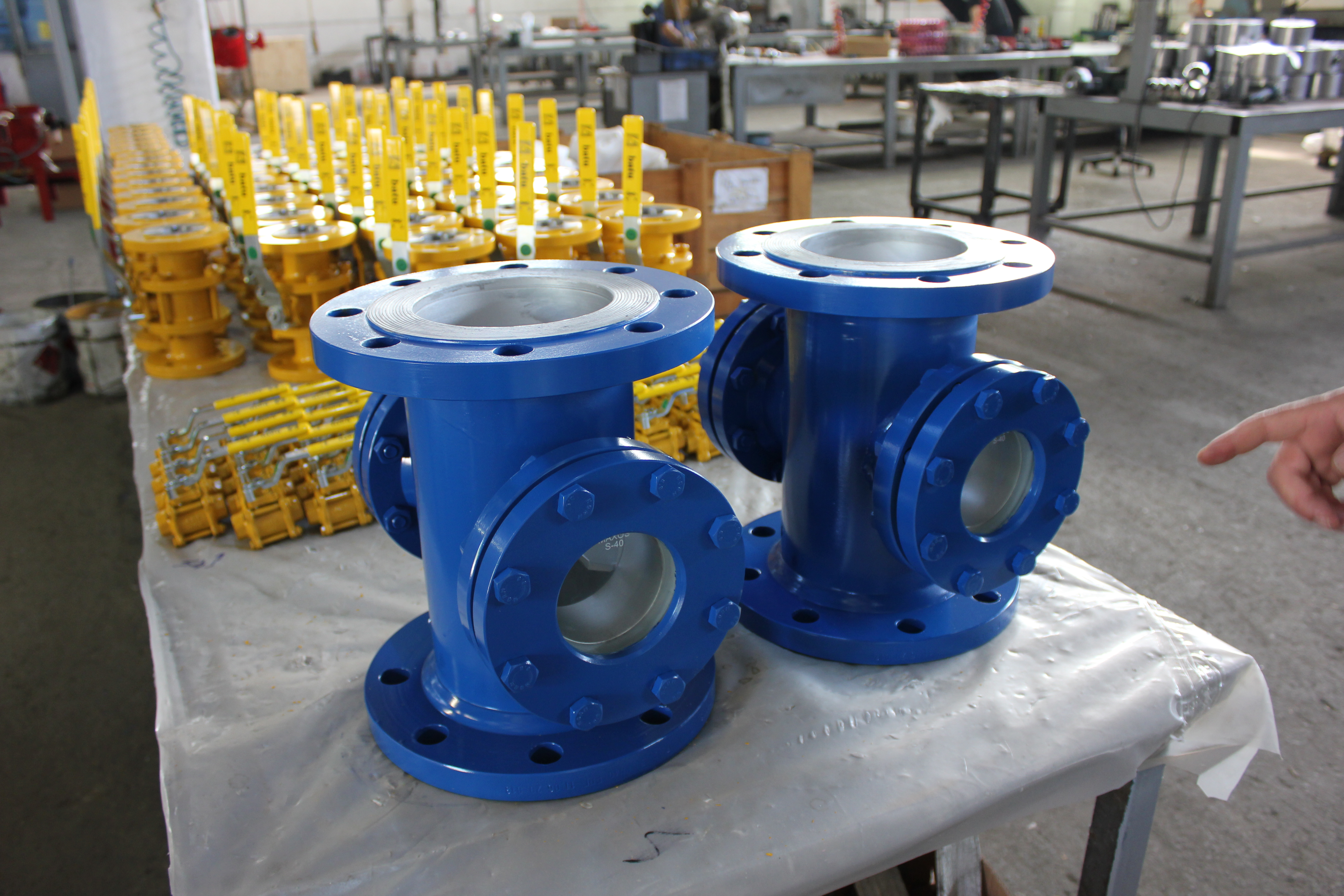
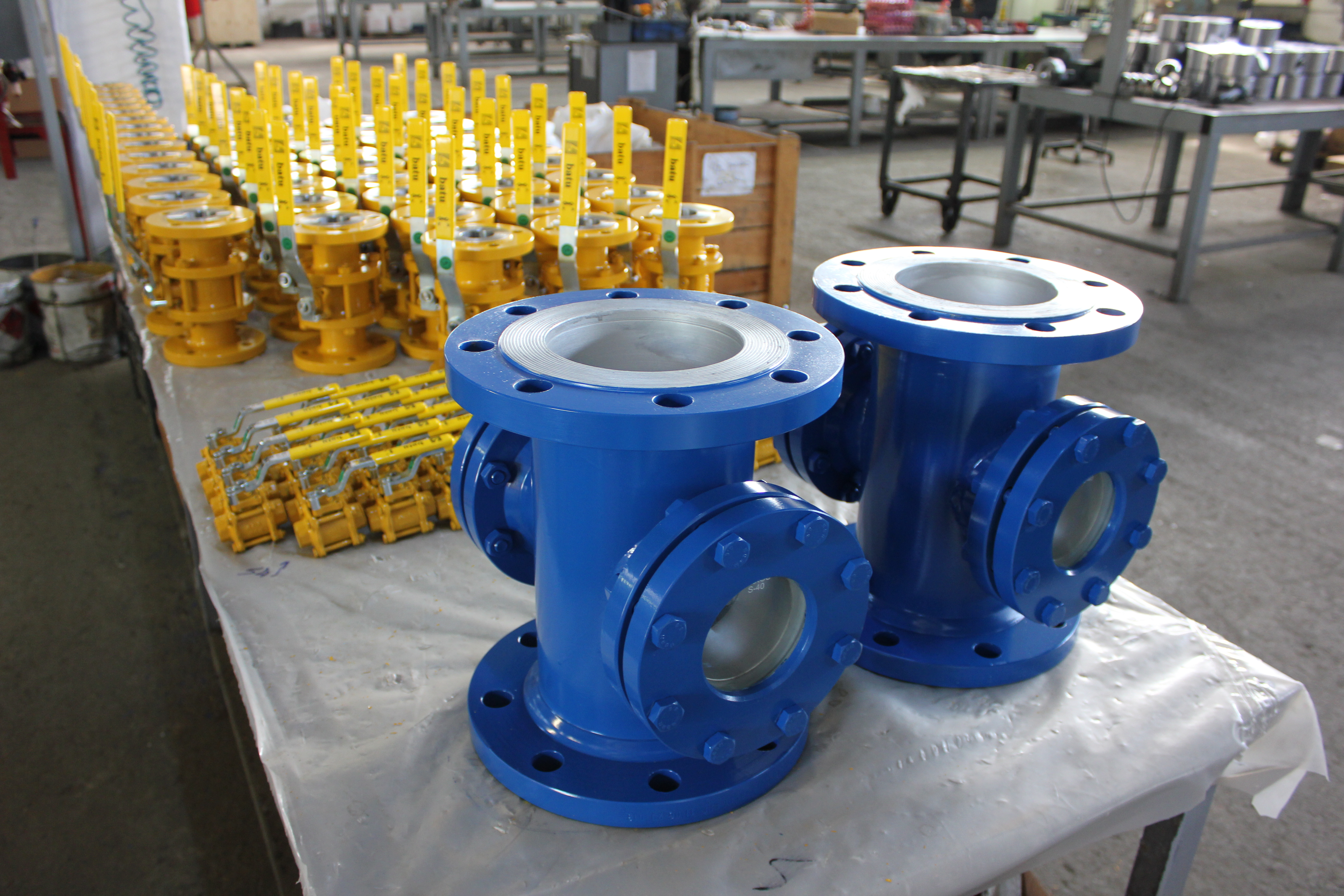
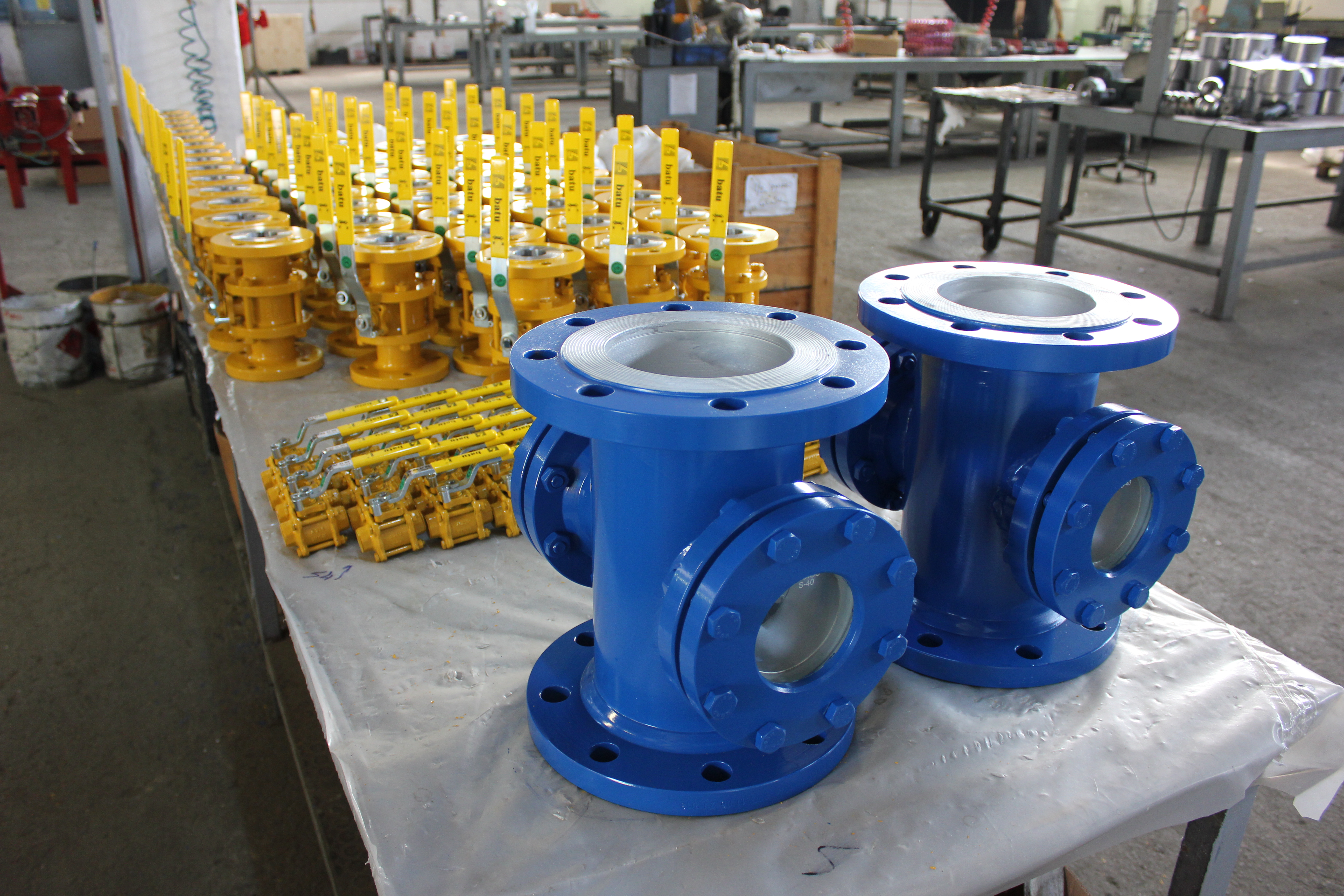
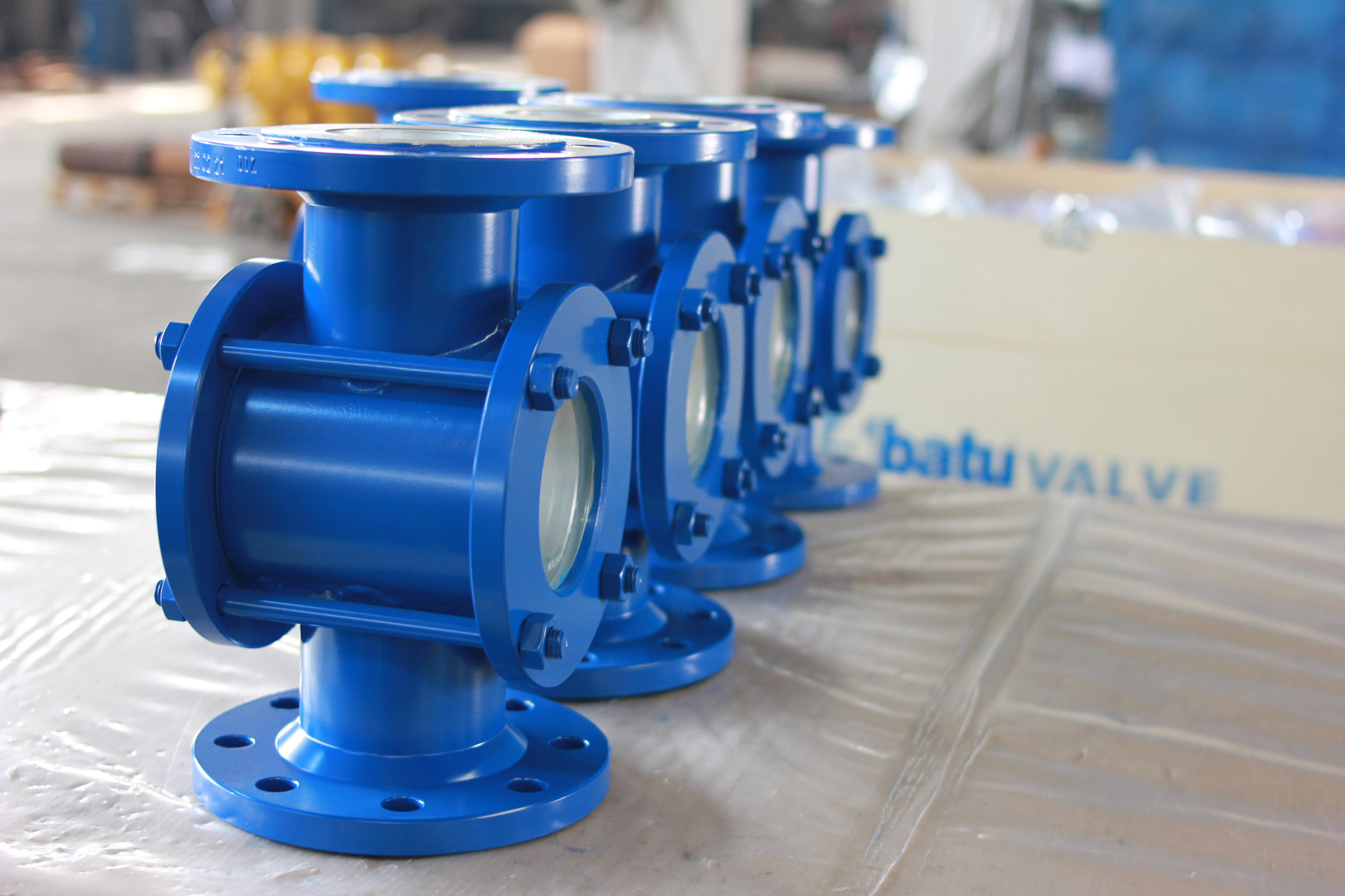
Flow Indicators (Sight Glasses) are used to monitor the flow in closed pipe circuits in different directions.
In order to fulfill the working principles of the FLOW INDICATOR, it will be possible to ensure that it is installed in accordance with its conditions and operated in an environment suitable for its conditions. Correct installation is also what keeps Flow Indicator Maintenance to a minimum.
The user is responsible for the problems and consequences arising from behaviors contrary to the specified issues, including those caused by neglected Flow Indicator Maintenance.
Considerations when selecting a sight glass
The Flow Indicator Maintenance instructions list the following selection criteria:
- The medium in which it will be used (the fluid passing through it) should be selected according to whether the fluid is liquid, gas, air or dark excess fluid containing solid particles and whether it is corrosive or not.
- Concentration and temperature of the fluid (max and min): the max temperature and min temperature of the fluid passing through the operating temperature valve must be known.
- Operating pressure (max operating pressure): max pressure of the fluid passing through the valve.
- Type of connection to the circuit: threaded, flanged, socketed, welded or unionized.
- Size or amount of fluid to be flowed per hour.
- Compliance with world standards TSE, API, DIN, EN.
- Valve passage type: full passage, reduction passage.
Considerations when installing the sight glass
Correct installation is the starting point of trouble-free Flow Indicator Maintenance; observe the requirements below.
For valve connection elements on the installation made
-
- It must be of suitable standard, pressure class and diameter.
- The axes of the pipes to be installed and the hole axes of the fitting to be used must be on the same axis. Example: if flange is used as connection element, bolt hole axes must be on the same axis. (Excessive stresses occurring on the Needle Valve due to such axis misalignments will jeopardize the tightness.)
- In flanged connections, bolts suitable for flange holes must be used.
- If the connection element is flange, the gaps are removed by tightening the bolts mutually, then they are tightened mutually at the given torque values.
- If needle valve space is left during installation, it should be left by calculating the length of the needle valve to be used and the length of the sealing elements.
- If the connection type will be threaded, the thread length on the pipe should not be less than the sight glass thread length.
For sight glass assembly sealing element in the installation
Sealing elements are the most frequent item in Flow Indicator Maintenance:
- Sealing element suitable for fluid type and pressure should be selected.
- The surfaces of the sealing element to be used in flange connections must be smooth.
- De-assembled, deformed sealing element should not be used, a new one should be installed.
- When installing the sealing element, care should be taken not to close the valve passage throat. (Sealing elements Klingerit, Teflon, 0-ring, rubber or rubber of suitable hardness.)
For valve installation in the installation
The Flow Indicator Maintenance instructions require the line to be clean before the unit goes in:
-
- Before sight glass installation, the line must be cleaned with compressed air or steam to remove any burrs, rust, foreign objects and dirt that may be present in the pipeline.
-
- For the new Needle Valve to be installed, the labels / covers on both flanges must be removed.
- The flange side of the sight glass to be installed in the installation, where the technical information is written, is mounted as the inlet. Then the other side is mounted to the installation without giving the opportunity to create tensile stress.
Points to be considered when using sight glass
Day-to-day use directly affects Flow Indicator Maintenance intervals:
-
- Remove the sight glass from its packaging when you will connect it to the installation.
-
- Operating conditions are specified on the sight glass as maximum working pressure in BAR.
- Flow Indicator Maintenance depends on correct orientation: when connecting the Flow Indicator to the installation, make sure that the direction arrow is in the direction of flow.
Tools and materials to be used
Flow Indicator Maintenance requires only a simple tool set: a double-ended wrench, suitable for connecting bolts and nuts.
Connection bolts used in flanges
The Flow Indicator Maintenance instructions give the following connection bolt dimensions for tailed flanges. L is the bolt length and Ø d the bolt diameter, both in millimetres.
| Valve size | PN 16 (DIN 2633 tailed flange) — L | PN 16 — Ø d | PN 40 (DIN 2635 tailed flange) — L | PN 40 — Ø d |
|---|---|---|---|---|
| DN 10 | 50 | 12 | 50 | 12 |
| DN 15 | 50 | 12 | 50 | 12 |
| DN 20 | 50 | 12 | 50 | 12 |
| DN 25 | 50 | 12 | 50 | 12 |
| DN 32 | 50 | 16 | 55 | 16 |
| DN 40 | 55 | 16 | 55 | 16 |
| DN 50 | 55 | 16 | 60 | 16 |
| DN 65 | 55 | 16 | 65 | 16 |
| DN 80 | 60 | 16 | 65 | 16 |
| DN 100 | 60 | 16 | 75 | 20 |
| DN 125 | 65 | 16 | 80 | 24 |
| DN 150 | 70 | 20 | 85 | 24 |
| DN 200 | 75 | 20 | 90 | 27 |
Conclusion
If you want your existing installation to work properly, placing a strainer (filter) in the main circuits will reduce operating costs.
The sight glass connected to the installation should be operated within the size and working pressure specified on the needle valve to prevent possible leaks and operating costs.
Flow Indicator Maintenance Documents
Flow Indicator Product Page
Flow Indicator Product Gallery